Home
Brushless Dc Motor Controller Wiring Diagram . E bike controller wiring diagram recent wiring diagram electric bike. By plug i mean the diagram that describes what each of the wires coming out.
Bld500 48v 500w Bldc Motor Driver Robotdigg from www.robotdigg.com Electric bicycle electric scooter electric motor electronics basics electrical wiring diagram big battery circuit diagram power cable wire. The post explains a simple variable frequency drive or vfd circuit which can be used for driving all single p circuit diagram electrical wiring diagram circuit Sensored brushless dc bldc motor control with pic16f877a. E bike controller wiring diagram recent wiring diagram electric bike. From a bldc controller, we also can see 3 corresponding.
(16) the brake switch is used to control the regenerative braking. (cw or ccw with optional reverse) designed for 36v brushless dc motors between 250w and 350w. 2018 24v36v48v 250w350w bldc motor speed controller 6 mosfet dual. Dc motor controller circuit diagram 👉 a stepper motor driver is a circuit that takes the pulse signals from a controller and converts them in to stepper motor motion. Chinese ebike controller wiring nonsense. (cw or ccw with optional reverse) designed for 36v brushless dc motors between 250w and 350w. 47 inspirational bldc motor controller circuit diagram.
Source: homemade-circuits.com The 48v w brushless dc tricycle motor main specification: (electric rpm = mechanical speed * motor pole pairs). 48 volt 1500/1600/1800 watt electric scooter/moped/bike brushless dc motor speed controller (cw only) designed for 48v brushless dc motors between 1500w and 1800w.
36v 800w set electric bike controller twist throttle brake lever. (16) the brake switch is used to control the regenerative braking. This drive circuitry is often known as electronic speed controller system or simply an esc.
48/72v brushless controller wiring diagram? Sensored brushless dc bldc motor control with pic16f877a. In this video we have shown the the connections of a 48v brushless dc motor with it's controller.
Source: images-na.ssl-images-amazon.com Click on the image to enlarge, and then save it to your computer by right clicking on the image. One common setup is called the full bridge drive circuit. (15) up to 40000 electric rpm.
Known as a power supply (converts 120 volts ac into 12v dc). A brushless dc motor controller ic has a smaller size, low production costs, and simplifies the design process. This simplifies motor construction, reducing its cost as well as eliminating the additional wiring and connections to the motor that would otherwise be needed to support the sensors, thus improving reliability.
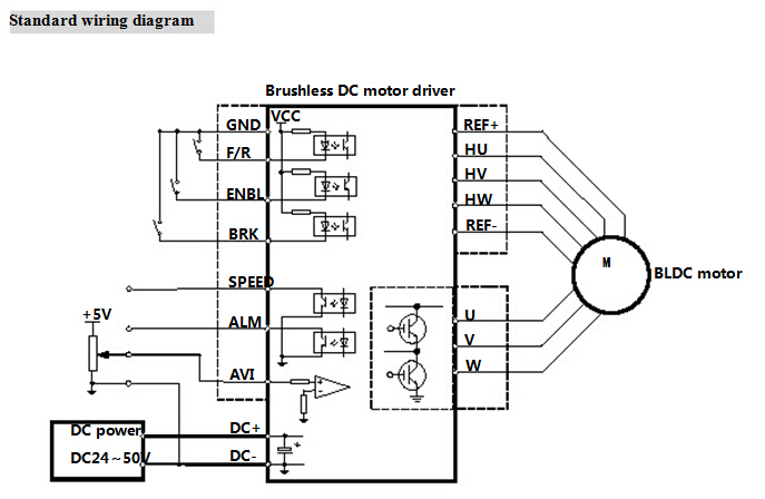
Updated brushless controller schematic 2018 motors 3phase inverters schematics. Motor terminal controller terminal red motor u white plastic case a pile Block diagram of a typical brushless dc motor control or drive system is shown in the following image.
Source: i.imgur.com Above that, the failure of one component will lead to the replacement of the entire bldc motor controller ic, not just this component. Sensored brushless dc bldc motor control with pic16f877a. Wiring diagram as well motor controller wiring diagram brushless.
Connections and wiring of brushless dc motor 48v subsequently controller. You need the electric bike controller wiring diagram to ensure the right wiring connections. Construction, working & applications of bldc (brushless dc motor) brushless dc motors (bldc) have been a much focused area for numerous motor manufacturers as these motors are increasingly the preferred choice in many applications, especially in the field of motor control technology.
The brushless dc (bldc) motor is becoming increasingly popular in sectors such as automotive (particularly electric vehicles (ev)), hvac, white goods and industrial because it does away with the mechanical commutator used in traditional motors, replacing it with an electronic device that improves the reliability and durability of the unit. When you buy a controller it typically looks like the above pic. Under voltage protection 30 volts.
Source: os.mbed.com From a bldc controller, we also can see 3 corresponding. Electric bicycle electric scooter electric motor electronics basics electrical wiring diagram big battery circuit diagram power cable wire. 2018 24v36v48v 250w350w bldc motor speed controller 6 mosfet dual.
Suggested electric fan wiring diagrams converting a 12 volt switch into a ground switch these diagrams show the use of relays, on/off sensors, on/off switches and on/off fan controllers. A bunch of unsightly wires coming out to handle all kinds of silly stuff such as cruise. The brushless dc (bldc) motor is becoming increasingly popular in sectors such as automotive (particularly electric vehicles (ev)), hvac, white goods and industrial because it does away with the mechanical commutator used in traditional motors, replacing it with an electronic device that improves the reliability and durability of the unit.
Sensored brushless dc bldc motor control with pic16f877a. Under voltage protection 30 volts. If you cannot see the pin number, you can take off the rubber cover.
Source: i.ytimg.com The 48v w brushless dc tricycle motor main specification: This 3 phase wires are used to changed the current direction to motor so that the motor can run continuously in the same direction. In this video we have shown the the connections of a 48v brushless dc motor with it's controller.
(14) support any poles of brushless motor. Whatsapp me on 9569956839 for any doubt, i'll try to help y. For common brushless dc motor, it has hall sensors, so the total motor wires is 8.
This simplifies motor construction, reducing its cost as well as eliminating the additional wiring and connections to the motor that would otherwise be needed to support the sensors, thus improving reliability. 5750 freego work manual manualzz kt lcd3 ebike display user 72v 3000w bldc motor kit with brushless controller for electric scooter e bike bicycle lcd5 8 5 niet opvouwbare verborgen draad. Sensored brushless dc bldc motor control with pic16f877a.
Source: i.imgur.com Replaces controllers with fewer connectors because most of the connectors are optional to use. When you buy a controller it typically looks like the above pic. The 48v w brushless dc tricycle motor main specification:
This drive circuitry is often known as electronic speed controller system or simply an esc. 36v 800w set electric bike controller twist throttle brake lever. Replaces controllers with fewer connectors because most of the connectors are optional to use.
Sensored brushless dc bldc motor control with pic16f877a. (15) up to 40000 electric rpm. Operates motor in clockwise direction only and is not reversible.
Thank you for reading about Brushless Dc Motor Controller Wiring Diagram , I hope this article is useful. For more useful information visit https://thesparklingreviews.com/